Moving up and down,
Several ways it could go,
Consistency's king
This is part 2 of my delta design/build log, detailing the linear carriages that I used. From a review, I'd say that there are only 3 viable options: rod-based, rail-based, wheel/roller-based. I eventually went with a rod-based solution, similar to what was used on Richrap's 3DR, though I'll admit that my final decision was due to a combination of frustration with my Rostock's cheapskate-based carriage and a set of linear rails that arrived broken, so I'm not trying to insist that rod-based solutions are optimal in any sense. Here are more comprehensive details on my thoughts regarding the different design options:
Wheel/Roller Carriages
Thanks to past initiatives like OpenBeam and Makerslide, it's become very economical to use extrusions that double as both structural support and linear guides. I'd argue that the wheel/roller-based carriage is the most common and popular solution right now, especially for delta machines. You can find them on designs like the DeltaPrintr, DeltaMaker, Rostock MAX/Orion, Cherry-Pi, Cerberus, Snowstock, Griffin, etc (just to name the ones that come to mind). This is probably the cheapest option, since it takes advantage of the existing frame and can be built from basic fasteners and laser-cut plates if desired. Also, it's easier to scale in size, since we wouldn't need any precision-machined components of significant size.
I've recently begun to dislike this design more and more for a couple of reasons:
- The carriage offset is larger than the other solutions. It's at least half the width of the extrusions, plus the inner clearance, and then the thickness of the carriage frame (whether printed or laser-cut).
- Carriage wheels need to be adjusted from time to time to ensure that the carriage is not too tight or loose. My Rostock MAX uses eccentric spacers to accommodate this adjustment. The adjustment itself isn't very time-consuming, but it's another thing I'd rather not be dealing with. I think a couple of designs just machine or print their carriage frames exactly, but I think that's a pretty flawed design approach. The Cerberus (and others, I'm sure) use a flexure to place a compliant load on one set of carriage wheels to ensure contact. I think this is pretty clever, but I don't have the means to cut/water-jet a carriage with a flexure, and I don't think I would trust a printed solution.
- I have no way of knowing when the wheels should be replaced. It's cool that we're even seeing wheel-based carriages on desktop mills like the Shapeoko/X-Carve, but I don't know that anyone's even done some rudimentary benchmarking on how long these wheels can be used until they're so worn out that they begin to affect performance.
Linear Rails
As you go up in price point in commercial delta printers (cartesian too), I've seen linear rails used more and more. The Printrbot Metal Plus has it for both the x-axis and y-axis motions. Commercial delta bots like the Spiderbot, Kossel Pro, and Atom3d (just to name a few) use these rails as well. It's possible that at a slightly higher price point and by ordering in bulk, it's a lot more reasonable to buy linear rails, but I think they're generally very expensive, especially as you begin to need longer lengths. That said, I should point out that while a lot of the commercial delta printers seem to extend the linear rail along the entire height of the printer, that's not necessary, since the carriage itself should have a minimum height for all valid points in its workspace. For me, I ordered a set of linear rails via Aliexpress sometime last year for $90+ (which I think was actually a cheap price at the time). One of them arrived cracked, and the other two didn't seem like they moved very smoothly, but I guess you get what you pay for.
I'm also a bit concerned that they're not really designed to handle large loads. The Printrbot Metal Plus still uses linear rods for the motion in z, and I think delta machines largely get away with using linear rails since the effector's so much lighter. With the way they're driven, linear rails are also always apply an offset load on the interface between the carriage and rail (the same could be said for most wheel-based carriage designs). However, compared to the wheel-based carriages, the carriage offset is lower, and they don't need to wrap around the extrusion support columns, so they'll accommodate enclosure walls a bit better, in my opinion.
Linear Rods
This is the tried and true approach, found in the original RepRap designs as well as the initial Rostock design, which used the rods as the primary supports as well. Since they're found in so many designs, it's pretty easy nowadays to find vendors that sell them at reasonable rates, though they, like linear rails, can also become quite pricey when trying to get longer lengths. I think the 3DR may be the only widely known design aside from the original Rostock to still use linear rods. There's also a Kossel Alt design that does the same, but I don't think it's gotten as much interest. The rods eat up a lot of the overall printer space, but they should decrease the carriage offset, and they can be designed such that the belts don't apply any offset load on the rods, which I think is nicer for long-term robustness.
I think the biggest issue with rods is their proper alignment in the final assembly. A single rod and linear bushing leaves 2 degrees of freedom: the desired motion, and an extra rotational degree of motion. Adding another rod and bushing then adds more constraints than we need. When (note I said when and not if) the rods are misaligned, something has to deflect/deform as the carriage moves up and down, or else the carriage will simply bind. For rods in delta designs, it's the rod that will deflect, since they're only constrained at the ends. This can suck a lot, as the carriage will bind near the bottom and top while still moving freely in the middle. The only way to adjust for this error (I think) is to not making the error during assembly in the first place. This can be done with shims or some set screws (and then space-filling adhesive) during construction, but ain't no one got time for that. For me, I think it'd be easier to just align the rods as vertically as possible, and then re-print the carriage pieces as necessary to minimize binding. A few guys in lab suggested a carriage block with a compliant element so that it could passively adjust for discrepancies between the rods, but as with the Cerberus wheel-based carriages, I wouldn't trust a printed flexural component, and I'd rather not add more complexity to any component unless absolutely necessary.
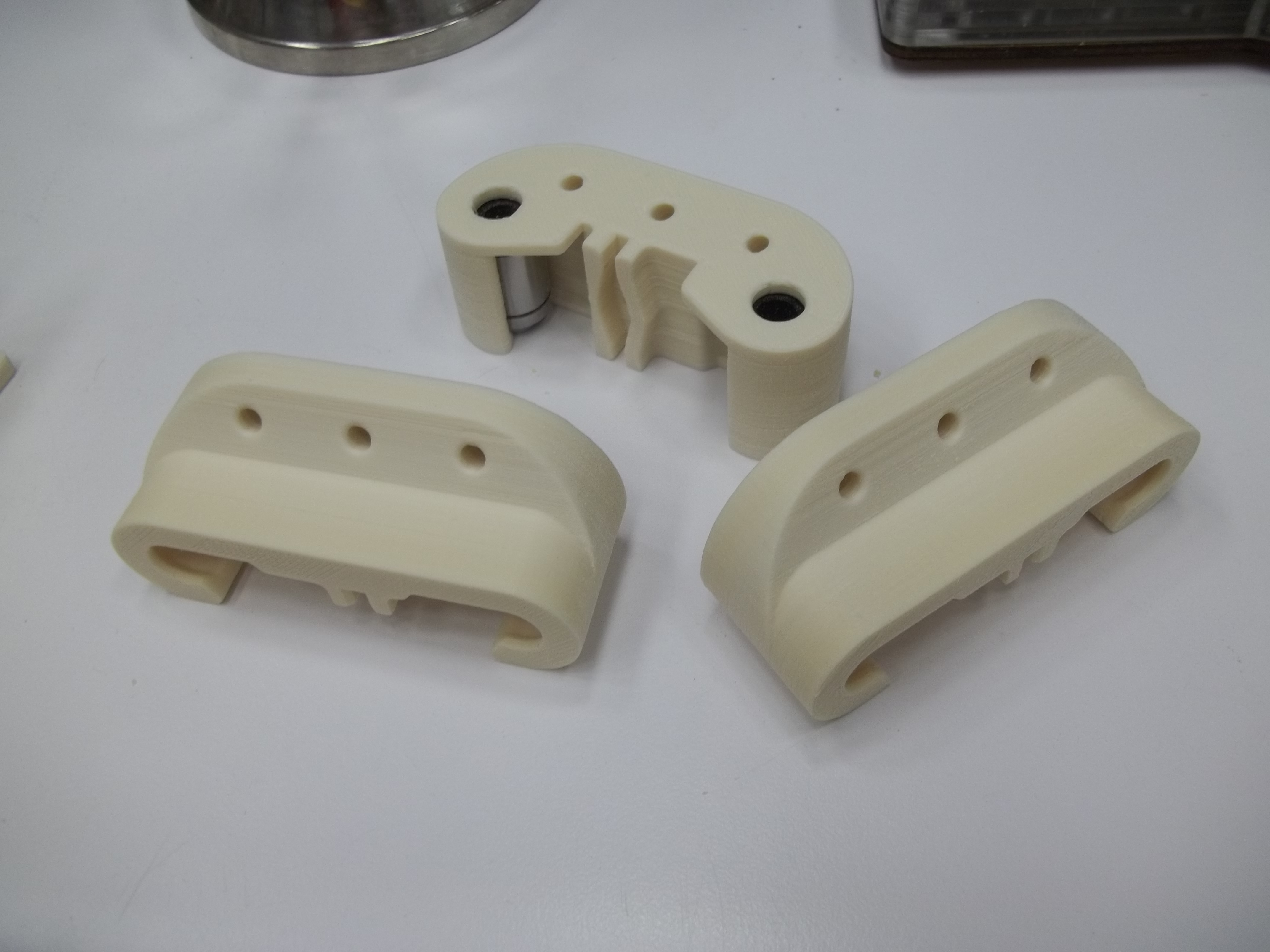
Resulting Carriage Design

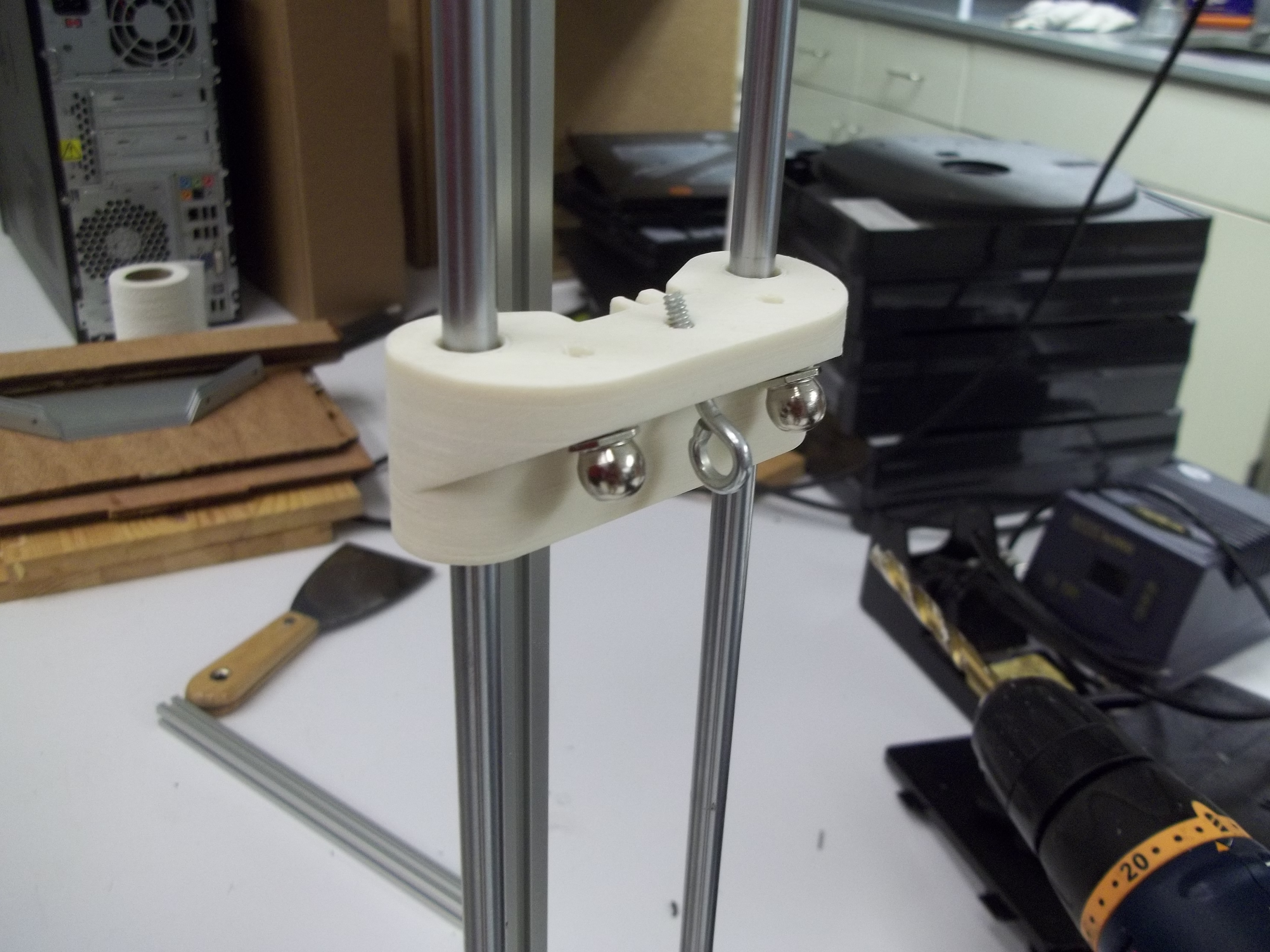
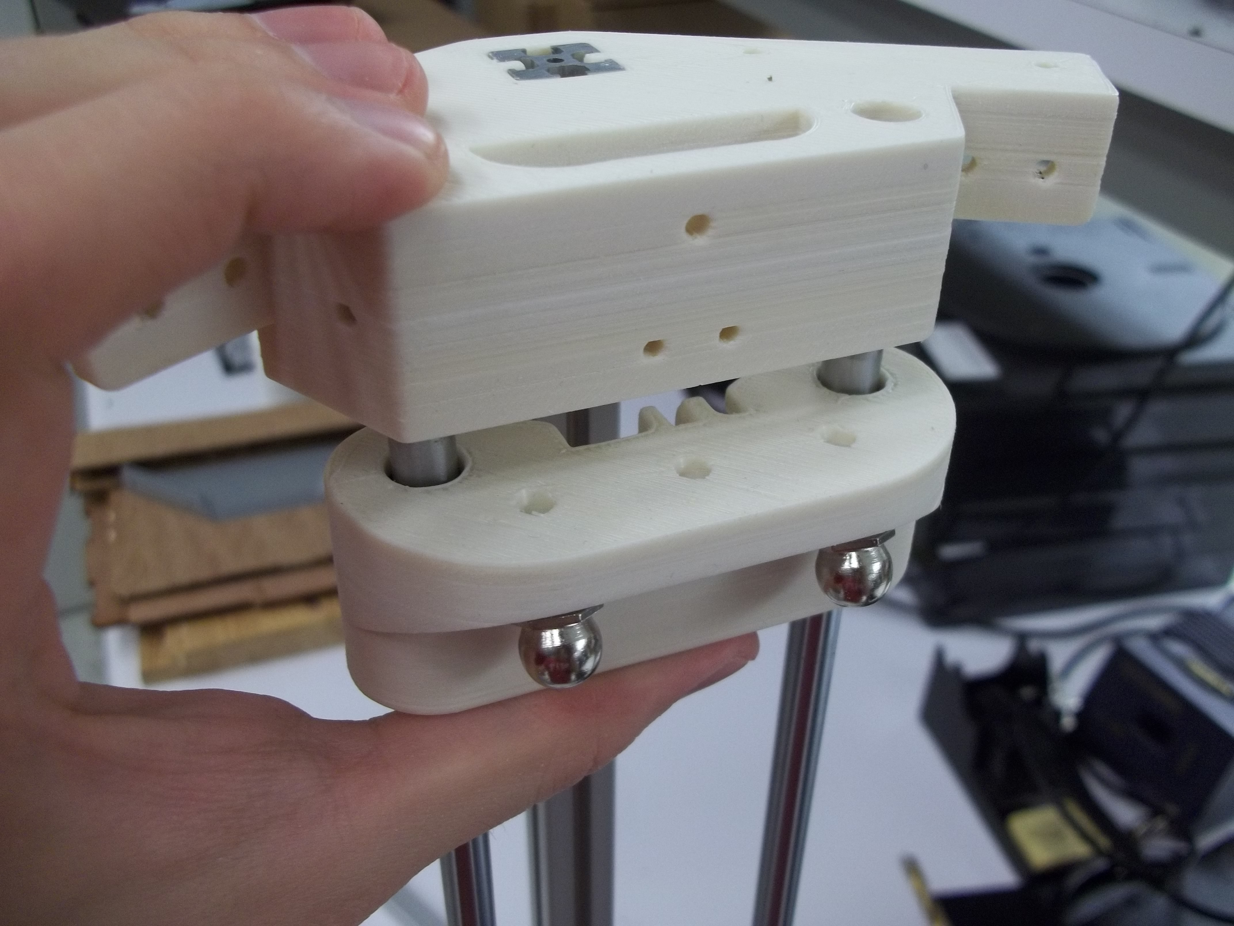
I went with a single-piece carriage frame, borrowing heavily from the Richrap variations from his different sizes of 3DR designs. I hate the idea of using zip-ties or a secondary part to lock the bearings in place, so I modified Richrap's design for his Mega 3DR carriage. It wraps around the bearings just enough, and along the appropriate arc, such that we don't need additional fasteners. The bearings sort of just pop in and are held quite well. Keep in mind that the bearings are constrained by both the carriage frame and the rods, so the carriage frame really only needs to keep the pair of bearings on the same level. In retrospect, I don't even think I needed as much of a wrap around the bearings as I did. I think I could've gotten away with just a carriage piece that pushed out between the two bearings, and that would've been enough. However, I'm pleased with the overall robustness of my carriages after they printed. They feel very solid without any noticeable flex anywhere.
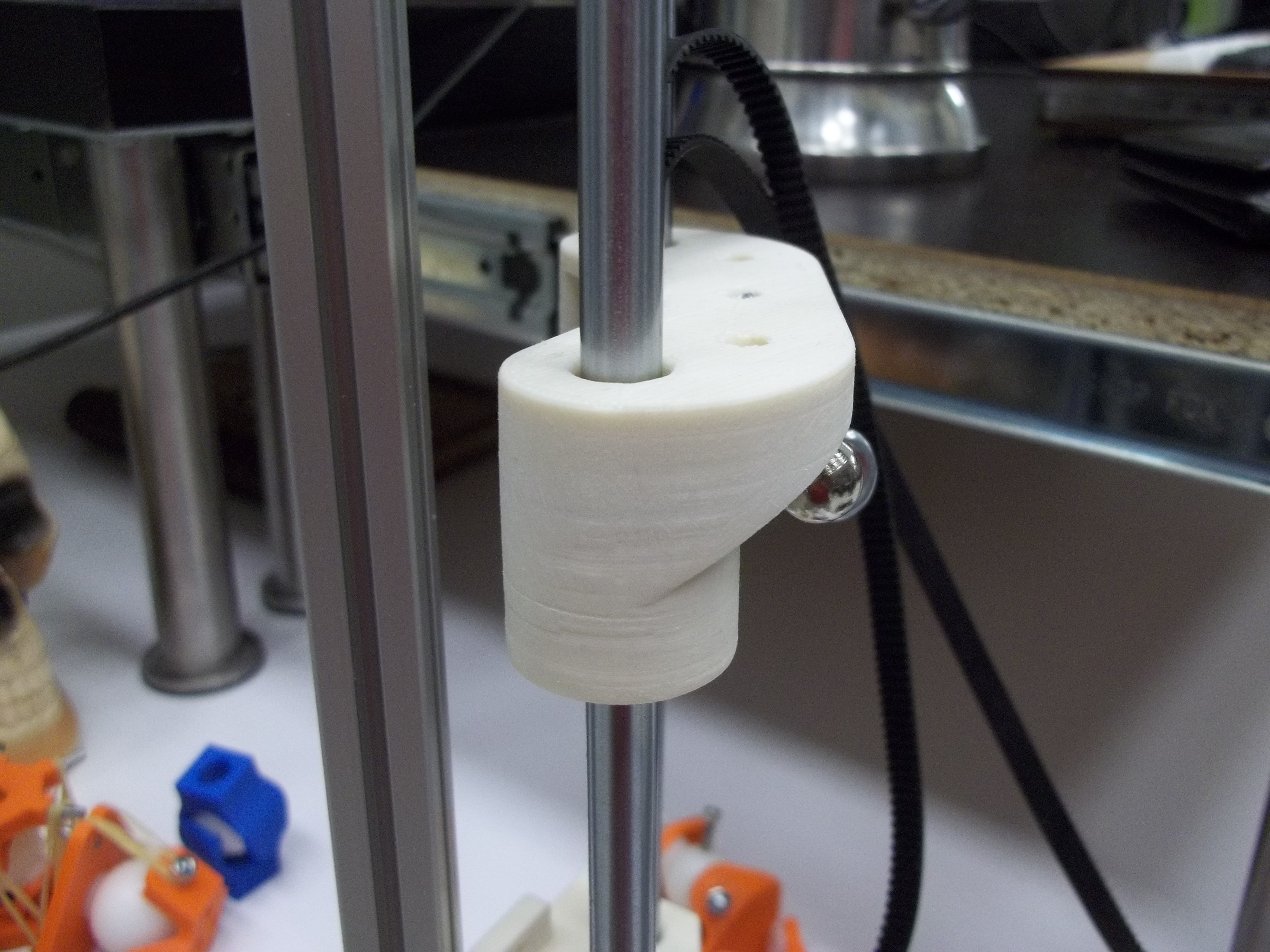
For better or for worse, I'm sticking with spherical ball joints instead of trying out Traxxas universal joints, though I'm planning on using the string-and-spring approach (via the Cherry-Pi) design as opposed to magnets this time around (hence the middle hole for tendon attachment). I also borrowed the belt attachment design from Cherry-Pi, where the walls pinch the belts wrapped around an inserted post or bolt. I found that I had enough clearance to use 4-40 and M3 heated-inserts without much difficulty during a test assembly.
There's no belt-tensioning system or mechanical leveling for endstops on the carriage. For calibrating tower heights, I plan on doing that purely in software (as I should've been doing all along, imo). The limit switch itself is just fixed to the top corner bracket, and it'll hit the top surface of the carriage frame. For belt-tensioning, I dislike having to tune either parts of the frame (ie. Kossel Mini, Rostock MAX) or have an additional mechanism riding on the carriage. There are nice timing belt tensioners (basically just torsion springs with bent legs) that should do the trick, and I'll probably just mount them beneath the carriage itself on the belt, where there should be plenty of clearance.
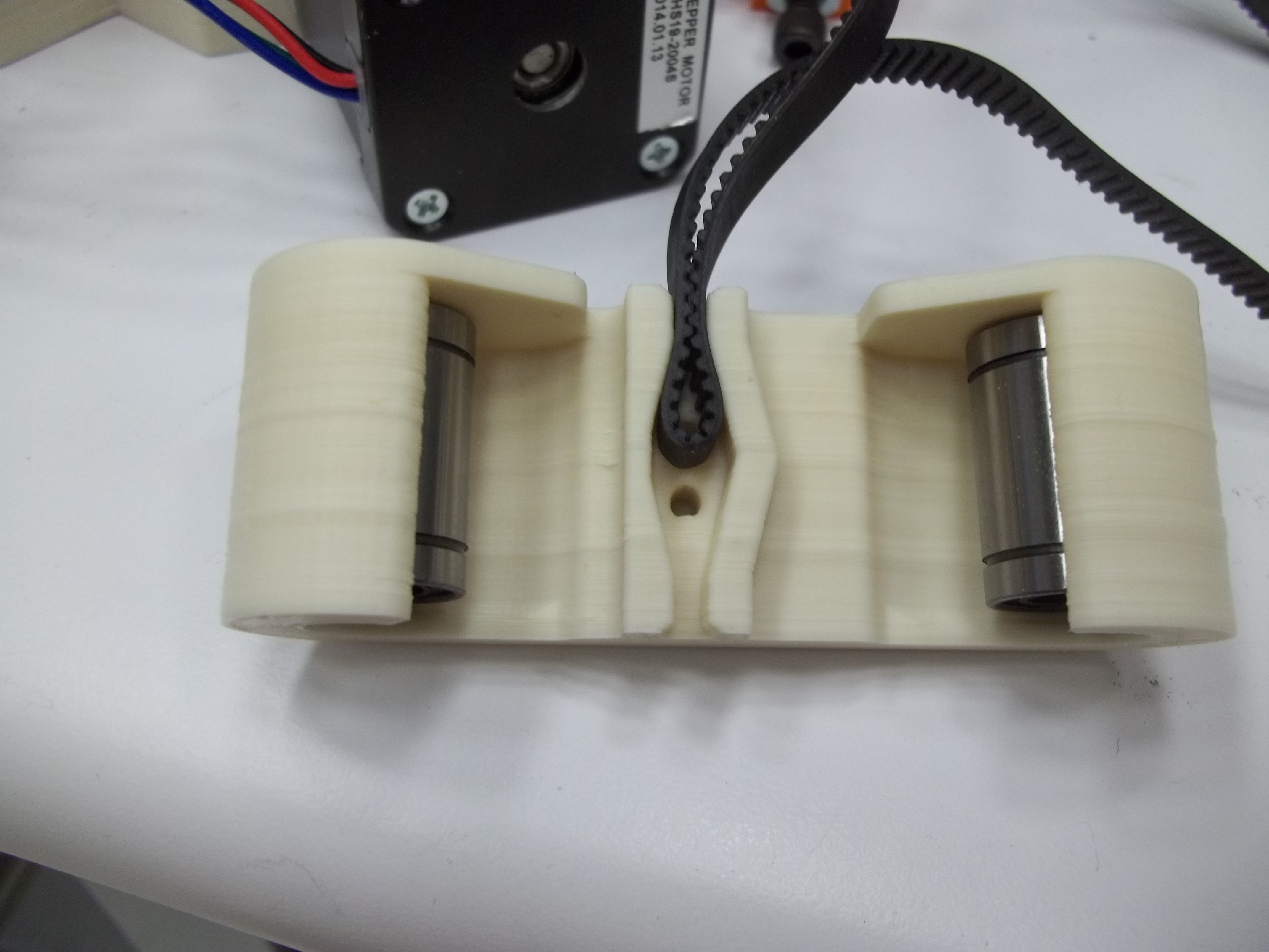
The carriages should be printable without any supports (if upside down), and the belts should be driving the carriage right between the linear rods such that there is minimal (if any) offset load as you would find with linear rails or wheel-based carriages. I had also considered using linear slide blocks (SCS8UU) along with laser-cut plates, since they come pre-threaded and seemed underutilized, but they turned out to be quite heavy (the 2 blocks alone weighed more than my printed carriage and all necessary fasteners).